 086-577-61800777 61806777
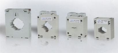
GENERAL
Current Transformer (C.T.) is used to transform the high AC current to small easlly manageable values.Ther're connectad with the Panel Meter or Relay and they can help to measure the current or pratect the equipments. Law voltage current transformers are man-ufaaured as of two types for measuring CT and protection CT.
MEASURING CT
Measuring current transformers are constructed to feed on other low voltage apparatus such as measuring instruments,relaysrwatt-hour meters (kW meter) and these type of current eransformers are maInly used 0.5 and 1 class to transfer the current from highest rated current to ra ted secondary current.
PROTECTION CT
Pratection current transformers are constructed to feed the protectian relay.These type of current tra n sfa rmers are mainly used 5 P.(Customer supplIed when required.)
REFERENCE STANDARDS
IEC60044-1,VDE0414-44-1,DIN57414,BS393B,BS7626,EN60044-1, GB1208-2009
SECURITY FACTOR
FS<5
MAXIMUM SYSTEM VOLTGE
720V AC
TEST VOLTAGE
3kV AC(1 min.)
FREQUENCY
50/60Hz
RATED SHORT-TIME THERMAL CURRENT
Ith = 60 x In
Ith linited by cable sizes or primary bus-bar for other case
RATED DYNAMIC CURRENT
Ldyn=2.5 x Ith
CONTINUOUS OVERLOAD
1.2 x In
OPERATING TEMPERATURE
-25℃ - +50℃
ACCURACY
Measuring 0.5; 1.0; 3.0 (Special accuracy upon request)
Protection 5P; IOP
BURDEN
Ranging from 1.5-30VA
RATED SECONDARY CURRENT
X/5A (x/lA upon request)
RATED PRIMARY CURRENT
Ranging up to 6000A
INSULATION
Class B for Casing type CT
Class A for Taplng type CT
CASING
Non-flammable,polycarbonate self extinguishing ABS/PC
TERMINAL MARKS
VO to UL94
Primary P1 & P2(K & L)
Secondary S1& S2 (K & L)
SELECTION OF THE CURRENT TRANSFORMER
To select the Current Transformer carrectly,the following points should be clarified:
. The application(for measuring or protection)
. The features of the working environment(indoor or outdoor,operating temperature,alr humidity etc...)
. Operation voltage and frequency
. Range of the primary current (maximum and minimum of the current to be measured)
. Dimension of the cable or bus bar
. Data of the overload
. Short circuit current
. Specification af the measuring device associated wIth the Current Transformer(accuracy,rated current,consumption etc.,.)
. The diameter and length of the cable,the cable which is used to connect the Current Transformer and assaciated measuring devic
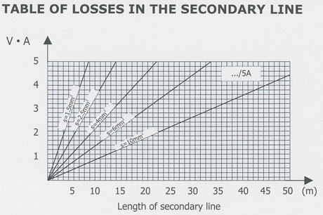
POWER LOSSES OF THE CT
In the practical application,the power generated by the primary current should be equal or bigger than the power requirement of the associated measuring device plus the consumption of the connecting line.
Losses in thd line, PL:
This is the power lost,through heat,generated by current through the resistance RL in the cables,inthe transformer's secondary circuit.
Factors to be taken into account:Secondary current:PL=RL ./2
Cable diameter:RL is inversely proportional to the square of the diameter
Cable tength:RL is proportional to the length of cabling(there and back)
Power:
the nominal apparent power (V . A)with a specified power factor,whichwas supplied by the Current Transformer,ta the secondary current with The assigned current when it is connected to its nominalload,sc(V . A)=ZC .(/SN)2 According to Standareds,for apparent powergreater than or equal to S VA,the power factor is 0.8 inductive.For apparent powerless then 5V, A the power factor is considered to be one(unity).
TABLE OF LOSSES IN THE SECONDARY LINE
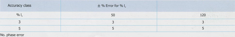
The percentage of error, produced in a transformer,is established by IEC60044-1.In measurement transfomers: 25% and 100% of nomin-aIPawe. ln protection tra n sfo rmers:l00% of nominal power.
ERROR LIMITS. TABLE 1. ACCURACY CLASSES
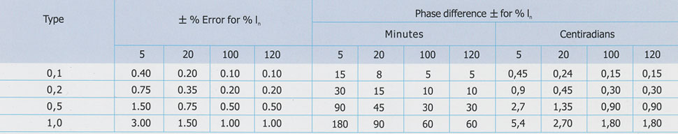
ERROR LIMITS. TABLE 2. ACCURACY CLASSES
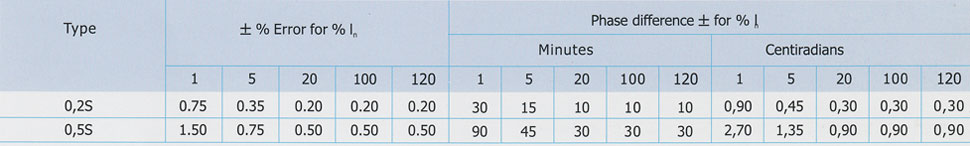
ERROR LIMITS. TABLE 3. ACCURACY CLASSES
FOR PROTECTION TRANSFORMERS

SATURATED CONDITION OF CURRENT TRANSFORMER
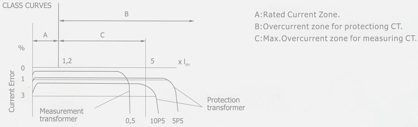
 The current transformer is saturated if the primary current, passing through the CT, is greater than the nominal rating of the CT.
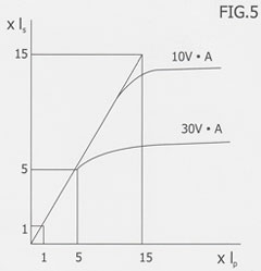
The linearity of current transformation, between the primary and secondary sides decreases, so error increases. The saturation of the transfo Rmer is inversely proportional to the load (fig. 5).
The dlfference between measuring and protectlon cu rrent tra nsformers is their behavior when an overload occu rs on the primary side Measuring CT is saturated when there is a primary current overload. In order to protect the equipment. on the secondary side, protection CT will not saturate until there is a very high current on the primary side.
A Class 5P15 protection transformer indicates that it has an accuracy rating of i- 1Vo that it does not become saturated until the primary Current reaches 15 times the nominal current rating of the CT
In measuring transformers, the SAFETY FACTOR "Fs" parameter indicates the excessive amperage on the primary side current in relation To the current sent to the measuring device on the secondary side.
APPLICATION NOTE
If the primary current is too small, to keep the same accuracy and autput, we can add primary winding, but the rated turns ratio should Be the same. For example, If the primary current is 50A, we can use 100/5A Current Transformer with the primary cu rrent be turned twice Which help to keep the same rated turns ratio(1:50 = 2:100).
CONSTRUCTION
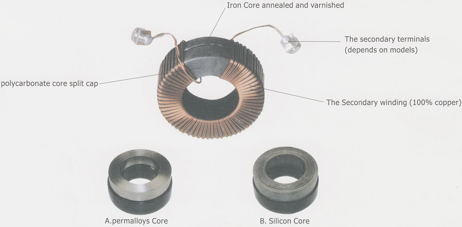
CT consist of primary winding.secondary winding,magnetTc core and insulated body.the high-grade silicon steel core Ts anealed,varnished then insulated with polycarbonate core caps.The secondary wInding is toroidally wound by hIgh precision semi-automatic machinery. For the tape wound ring type current transformer,the PEW coated windings are then covered with PVS tapes. For the encapsulated type current transformer,the w7ndings are enclosed in a compact and heat resistant split cap.
KIND REMINDER:
. Improper selection,installation or operation can cause danger to personal securityl
. Don t open the secondary circuit when the current is available in the primary circuIt. Or it will cause high voltage which is dangerous to personal securityl
. resista nce of current transformer is very low, so that secondary winding of current transformer can be operated as a shortcircuit, when required Tn test operation.Otherwise,this condition causes high voltage and can be dangerous during usage.
. When selecting a current tra n sfo rme r, it is important to co nsider the power absobed by the cables connected betweent the CT secon d a ry term7nals and thf measuring instrument. The resulta nt ca ble burden should be added to the equipment burden,and the total should not exceed the available VA of the CT
. P1(k) must face the supply feeder, a nd P2 ( L) must fa ce the load.lt is also important to ensure that secodary connections are made in accordance With instrument diagrams. The secondary terminals of the CT must NOT be open-circuled on load as dangerouly high voltages may be present under these conditions. Lt is recommended that one side of the secondary windings is earthed.